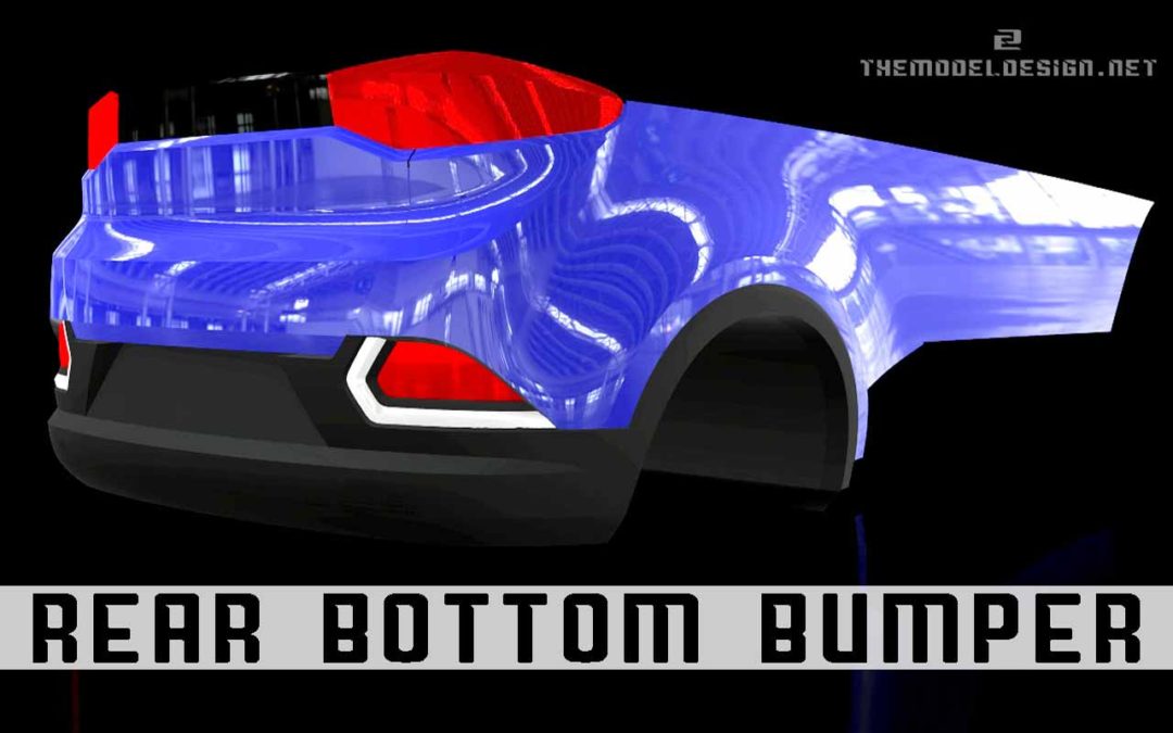
Here comes another tutorial on 3D digital modeling detailed creation of an Automotive Rear Bumper. Beginners and Pros in digital modeling will find this Hands-on-Practice, Step-by-Step modeling guide helpful. All of the gray color will be modeled in this tutorial. This includes the reverse and fog lamps cut-outs.
For some cool free cool stuff click here: Do This and Take Your 3D Modeling to Automotive Level Today
Or here: Alias Modeling Free Tutorial – 3D Model PDF Free Download
Tutorial Overview
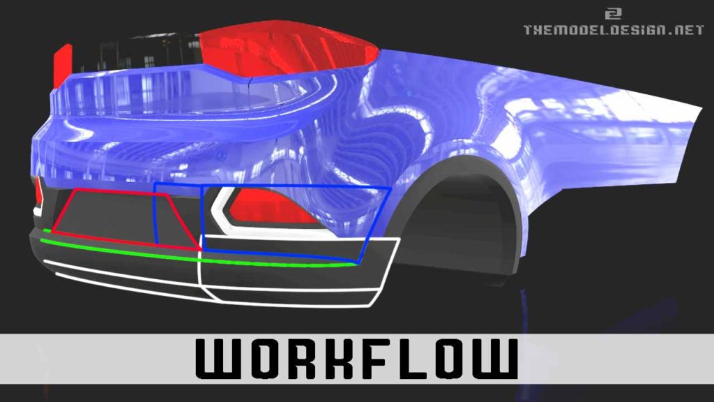
A quick word on tutorial’s basic workflow. We begin at the bottom area and move upwards. This includes building main slab surfaces market with white color. Second step is to build the threshold of green surfaces, followed by blue patches. Finally, we model the number plate surface – red color, and at the end of that we look through our geometry yet again to search for some possible areas of improvements….and we find at least one.
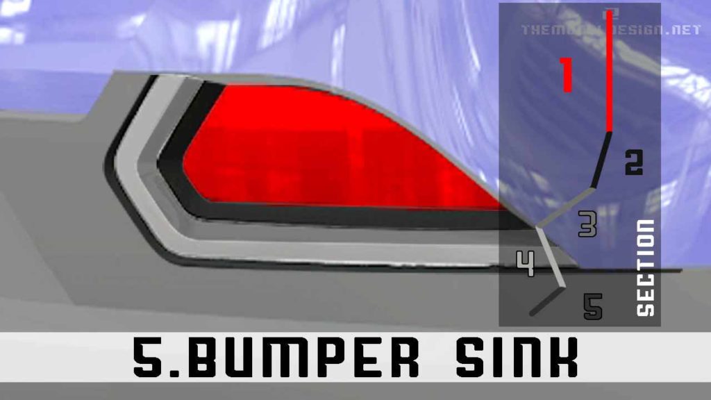
In the second part of the video we move on the cut-outs. I show you a very efficient method of creating consistent geometry. We are going to have 5 elevation changes and 5 different surfaces. 1st one is the lamp main surface, 2nd is our plastic trim component surface, Our shiny chrome, snap-in part consists of surface 3 and 4, and finally the last feature, the bumper sink which is surface 5.
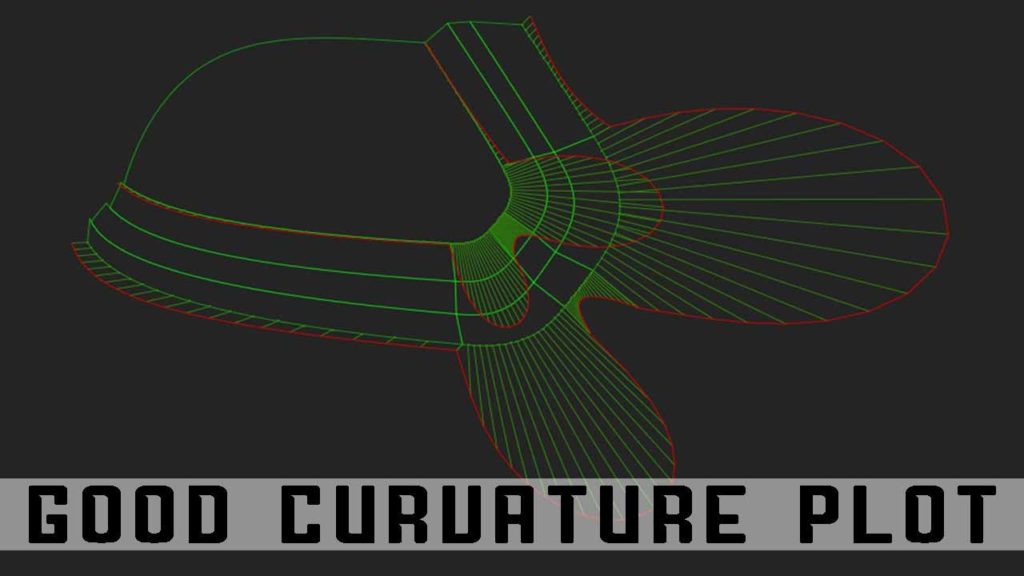
It is also worth mentioning that I use the example of these components to walk you through how I build high quality curves to achieve a refined looking product.
Alias Modeling – Part 1
Let’s turn on the scan and start creating our basic surfaces. But first let’s just ask for a curve, press and hold ALT button and just move our curve to the place where you want it to be. Do just like I did many times before. If you need, you can go to our previous lessons to see the reverse modeling process more in depth.
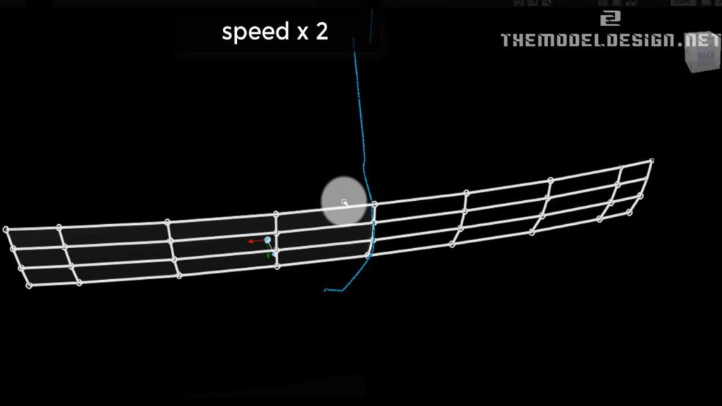
As you can see, I make the 7 degrees curve and detach it in the middle, just to have enough ‘sculptability’ to stay true to our scan. At this point I think that a degree 7 curve might be too much, but I will just keep it like this. You can try to make 5 if you feel like. I create this surface with one extra span and 7 degrees, and I use this curve to project onto my newly built surface and trim away the half. By working through the center you always get a perfect G3 running through the middle.
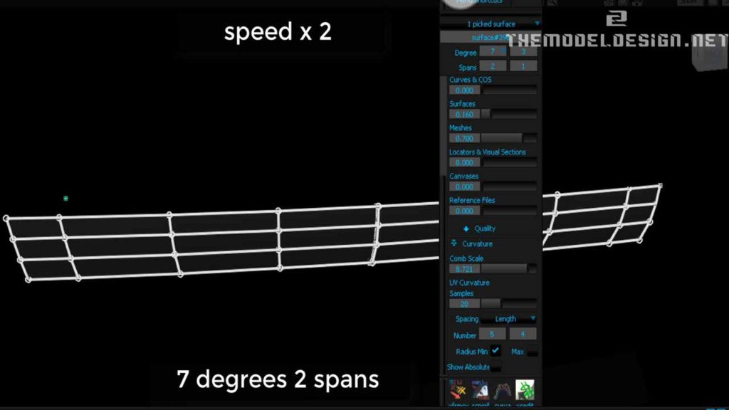
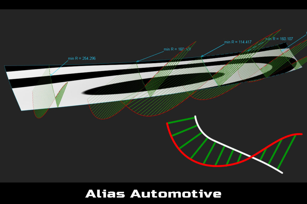
The time has come for creating another surface. At this point curvature comb plot is important. We can have a G3 continuity. A typical workflow in an automotive industry around this corner blend would be to make this patch 6 degrees. The additional 6th degree would shoot out very unnaturally, but I prefer keeping everything more natural with 7 degrees.
In fact reverse engineering has this attribute that you always end up with heavier geometry as if you were to model it off the blueprints or photographs, because staying true to the scan requires more accuracy and therefore more CVs.
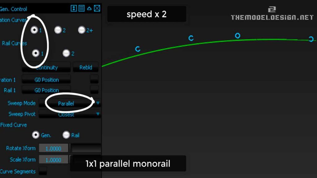
After all, Just remember, you need to do whatever it takes to achieve the shape, and adding more CVs will help you with achieving that. We have our curve. Let’s create the rail surface. Select 1 x 1 mono-rail and make it parallel. The angle between these two perpendicular hulls is constant throughout.
Alias Modeling – Part 2
Moving on to the sill surface. What is important during the creation? Similarly to our tailgate from previous videos, sill has to have a change of direction from positive to negative. Only this way we are able to satisfy the zebra requirements. We also need to ensure some necessary lead-in (acceleration) for the fillet geometry between the sill and the number plate surface.
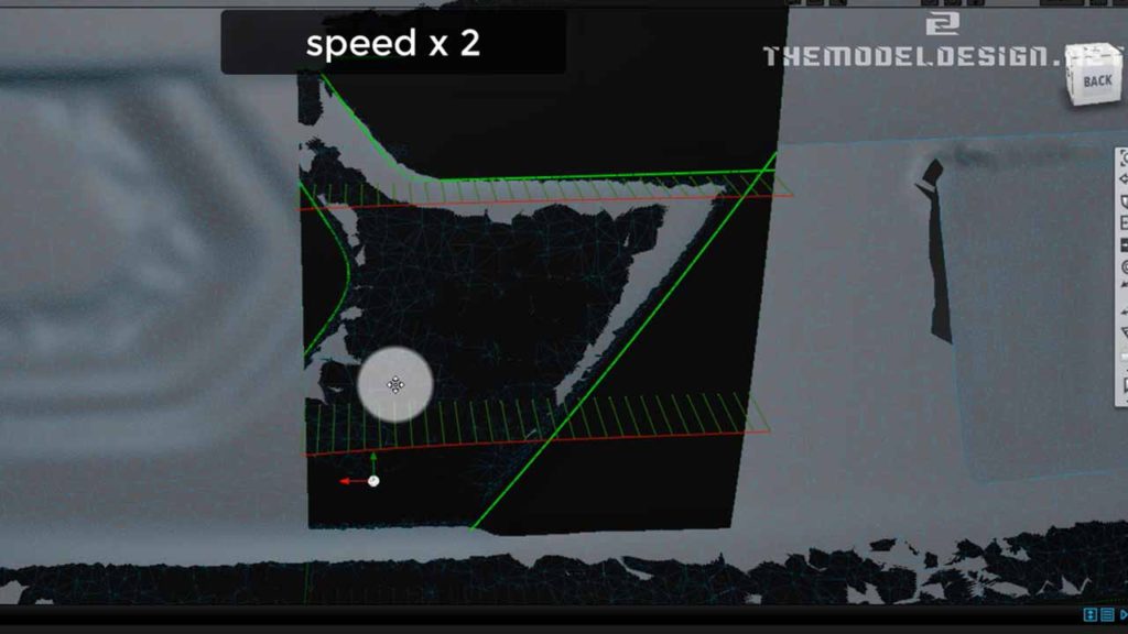
It is very important to have a good, consistent theoretical intersection. Unfortunately, there is a lot of wobbling going on in the scan geometry. Building surfaces around such data is tricky not because of technicalities of the surface, but because of the scan’s low quality. I wasn’t sure where the ‘theoreticals’ were located. In the automotive industry is it quite normal though, that you often work to scanned clay data which is not accurate at all, and you have to workout the right doings.
Geometry of Main Bumper Surfaces are relatively straightforward. I apply the same building method as I used for all other patches around the bumper. And I just pay attention to having a strong theoretical intersection.
It is also a good idea to have our patches finishing off at exact locations. The intersecting patches should ideally be of the same lengths. If you want to make them at exactly the same spot just use the intersect tool to get a COS (Curve On Surface) and then use an extend tool to snap edges to the exact spot.
There is no much to the comb curvature plot. Surfaces are very basic, however, we can still add a little of story to them. Firstly, make them more than 3 degrees. I think that adding one more degree would do the job. Now do some sliding just to introduce a little of lead-in. At this moment we are talking about details. If you get details right your model will look so much better. Details are important, and it is worth paying attention or simply being aware about these minor changes that you can make to your model.
Alias Modeling – Part 3
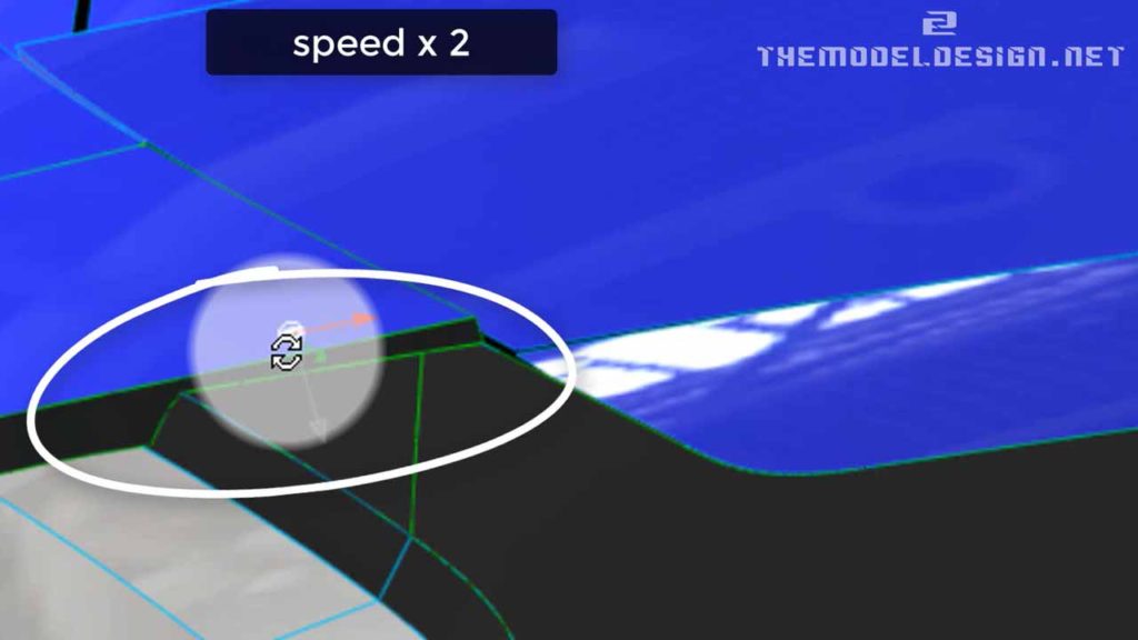
Next, I create the lamp cut-out. I untrim and offset the corner blend. I do this because I create some distance reference before I build the geometry. Predictably, I have some issues with my offset surface. I can manually slide CVs and maybe slightly push them out or pull them in. I don’t use the smooth tool because it affects the surface too much.
Just not to make this tutorial too long, I speed up the process and only discuss main workflow of building the first three thresholds. Creation of all of the other steps would be very similar. Basically it would be all about creating reference planes and projecting the curves onto them. Once we have the curves on our reference surfaces, we could align the edges of surfaces onto them.
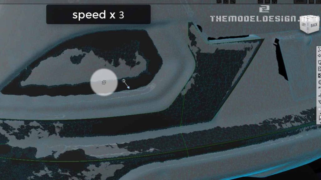
Aligning the patches to the trimmed edges will ensure that our reference surfaces are consistent throughout. By doing this, I dramatically increase the rate of being successful. Highlights are much more predictable.
Ask for a curve, add degrees, grab and pull up the last and also the second to last CVs. If needed, I can tweak other CVs but just ever so slightly. Using this method I can achieve a nice comb plot. The result is actually not too bad. I obtain good G2’s and even almost G3’s with a lot of lead-in. Because of this I obtain a good looking, organic form of the cut-out components with no visible dips or bulges. Volume and highlights are also good, there is no wobbling, and no inconsistency.
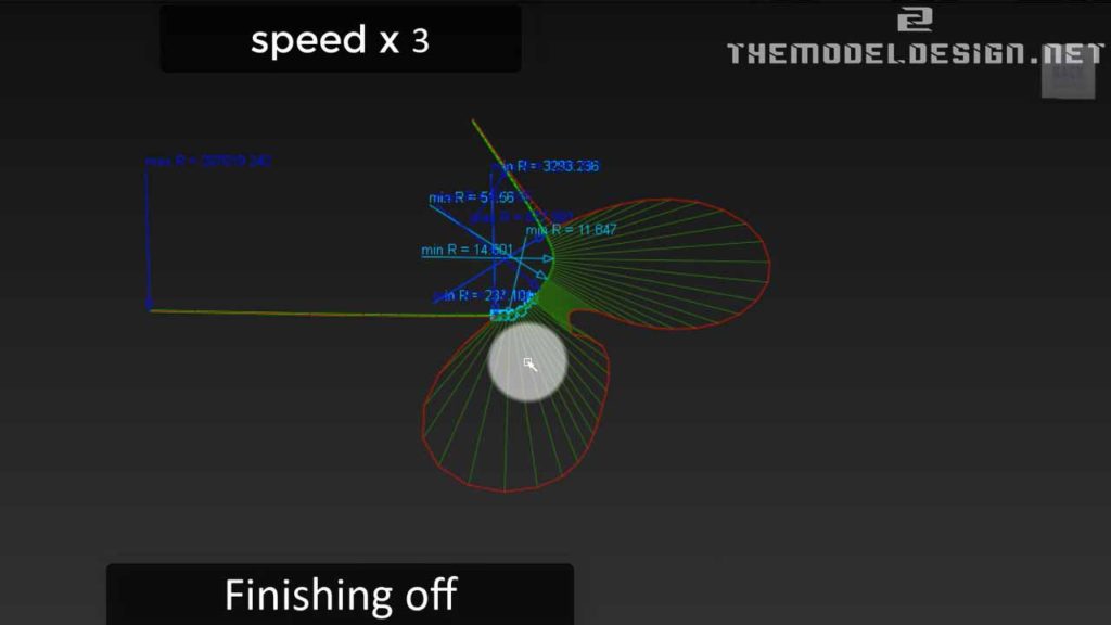
At last I created the number plate surface. I didn’t record it because it simply was just a matter of building almost a planar surface with little crown and minimum curvature.
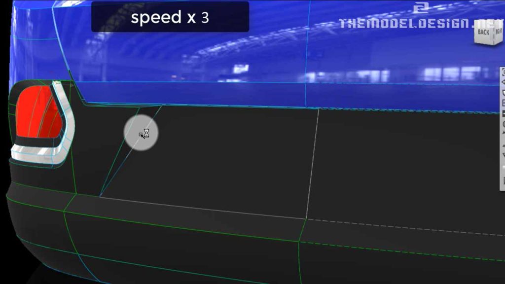
Possible Topology Improvements
There is an issue with our topology. It is nothing serious, but I think it is worth mentioning. If you watched my previous video: rear bumper 2 video you will know that I decided to remove the additional surface around the blend corner, and now I feel like I should have kept it. That little portion was an elongation of the tailgate, which is actually very consistent and could be used to anchor our blend corner. It might be worth going back, offsetting the tailgate surface, tweaking to suit our scan better and taking a chunk of it to make it an anchor geometry. By doing so, out step distance will be consistent. If you are after the data, it is free to download on my blog and you can have a go yourself.
Good luck.
