The process of designing, modeling and manufacturing products is always very exciting. But product creation can also rise tones of questions and concerns. Without a thorough guide and experience, it is hard to know the exact directions on the right doings. Every entrepreneurial product designer might be theoretically 100% ready to take upon new challenges. However, life brings surprises when we least expect them. Each product is unique in its style, function and purpose. Therefore, defining a helpful guide which is a mixture of theory and practice helps overcome the unknown challenges.
How to go about designing, 3d modeling and manufacturing a product idea? Understand intricacies of an advent of a new product is the only way to succeed. There is a sketch design ideation phase, where the invention receives desired styling, form and visual advantageous attributes. Designers’ input might include: aesthetics expectations and DNA inheritance. All of this bonds with 3d modeling in the second step. Here, the 2d flat work, through designer-modeler collaboration, is shaped up into a 3d data. Modeling often incorporates many design iterations and various scales clay models with tape drawings. Initial package drawings and longitudinal sections are introduced by engineering department. In the last step, digital model is developed further for surface quality, volume and highlights, and is investigated against all technical requirements. Engineering input includes: material and wall thickness, gap and flush values, hard point package stuck-up.
Designing and making a product. All things considered
Styling and engineering are constantly battling against each other. They are a bit like left and right brain hemispheres. In vehicle design, this battle is particularly apparent, resulting in a continuous series of compromises. Considerations of no-compromise styling are often being dragged down by available space, technology or simply financial reasons. As an every human being decides whether a product is desirable in a few milliseconds based on its look, the fine styling tends to win over sound engineering and safety in design.

Styling considerations often dictate the shape and position of bumpers, which are thought to be the most important safety feature to the vehicle. Little functionality can be found in bullet-like components of the bumpers and bumper guards of some cars. What’s more, they present needless hazards to pedestrians, as do some other chrome embellishments, including oversized grilles or complete front facia shaped for optimal aerodynamic efficiency and brand identity.

Design and form in product design might be brought about wholly by styling or by engineering, or some mixture of both. The safest and most clever strategy worshiped by various manufacturers is to claim that the styling is a result from an engineering change, and that the two work together in perfect harmony, supplementing one another.
“McLaren 765LT Fearless Engineering” video presents styling-engineering win-win situation of 80kg weight loss on many sub-components with the newly redesigned and restyled bodywork.
Bugatti, in turn, states that its new aero pack helps new Bugatti SUPERSPORT achieve higher top speed. It appears that engineering advances for performance are often as great as they are pictured.
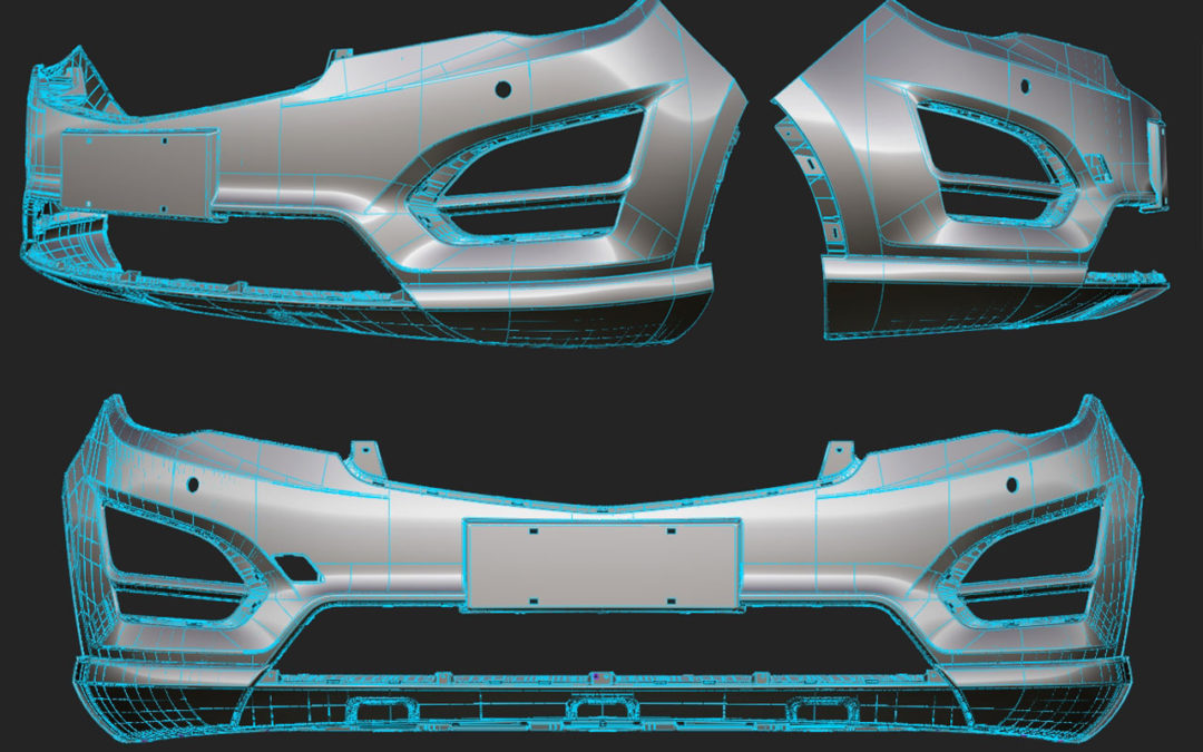
Making of Front bumper. Design and development
For passenger cars, the bumper assembly consists of the plastic cover and impact absorbing mechanism. Having satisfied the approach angle, its elevation must span over the “bumper height band”, which ranges from 406mm to 508mm above the ground. The longitudinal position of the bumper-impact surface must ensure enough crush margin for the occupants’ feet at high speed of up to 65kph of frontal impact. Components which won’t significantly deform on impact i.e. motor, transmission are also taken into distance consideration. The equation figures depend on collision specs and the fabrication cost limitations of the design.
Passenger vehicles, at low speed impact requirements, with bumpers of average cost and weight have about 50-70mm of surface offset. However, on the example of Mini Cooper, it is apparent that manufacturers challenge these figures and bench mark vehicles with smaller offsets. The front facia profile should be shaped to meet pedestrian protection safety requirements, which might be tricky, considering current styling trends and some potentially trivial issues, such as latching structures or hinges. What’s more, the leading edge of front grille is very often restricted in height and width by cooling module.

Follow the steps to get Your product idea styled, built and made
Step 1: Sketching – Styling
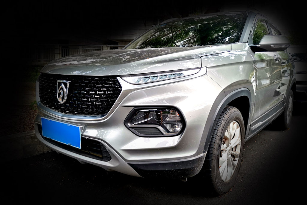
Sketching – no matter what phase the project is in, sketching is an ongoing process. Is begins rather loosely, ideas being thrown in, and might terminate simultaneously or shortly before the 3d digital model is complete. It is quantity, not quality that matters in the initial stages. Quality is always determined later in the step two at 3d modeling stage. Getting as many ideas out, at the beginning, is the critical part, and for that judgement should be put aside. Turn off rationality, common sense indicator not only of your own ideas but of other people proposals. If you see something that you have not seen before you are making a progress. Novelty, not relevance takes priority, as relevance or rational thinking is something that people do really well every day. The novelty is the most precious, as it is something that we tend to lose as we step into adulthood. Showing to people what they might potentially like or even desire is like hitting a bull’s eye. Present them something which they have never seen before. Find the sweet spot between novelty, relevance and innovation. When comes to the bumper novelty, an ordinary, passenger car: Citroen C4 comes to mind, having its front headlamp clusters totally redesigned and re-positioned. In China, similar design attitude was embraced by Bao Jun 510.
Sketching might also mean rough 3d modeling. As the basic new ideas appear on computer screen, it may also be worth discussing the new possibilities with the engineering team at an early stage of the project. The process of 3D sketching can be started by blocking the basic proportions and adding in some novelty elements of the package.
Consider:
- Did designer lose his/hers audience? During design turmoil, does the best idea prevail?
- To what extend are highlights and proportions exaggerated or distorted?
- What design changes will future bring?
- Allow some maneuverability for future iterations? Design iteration circle – set of design iterations over period of time. Working out how the product or part styling will progress and evolve over time. How much is restyling going to impact mold design? Typical practice is to redesign bumpers by removing material from the existing mold, which means adding more volume to the design. Consequently, bumpers grow exponentially bigger.
- Color split – typically 3 colors split. Bodywork color, black trim color, silver metal imitation color, in case of sports cars splitter (photo)

Step 2: Styling – Technical input – 3D modeling
In this phase, ideation sketches become more “nailed down”. They receive further definition. Initial, best ideas are being pursued and refined in 3D program. Here, so called; “what designer had in mind” term starts to see the light in a tunnel. The tones of “paperwork” reap the harvest. The broad focus is gradually narrowing down by right interpretation, and clear idea communication to the decision makers on the project.
At this stage, don’t overlook details! They might be a part of the big, unseen idea. Sometimes unique details, usually something like bespoke looking highlights, chrome parts arrangement or, most recently, light clusters are worth taking additional time to break out some brave sketches to complete the voyage.
At the same time, more advanced, technical input is provided based on package drawings. The initial data input is usually developed accurately in a 3D CAD system, and, as project progresses, it is clearly communicated to everyone involved.
Image is worth a thousand words, therefore the communication is done effectively in the form of 2D graphic depictions. An automotive studio engineer is to supply the design team with hard point and cross-sections, which are generated from the pre-existing package.
The data minimizes the risk of “styled surface – hard point clash” to virtually zero. It also helps understand logic behind the concept’s architecture, and indicate what engineering changes are and aren’t possible. As the result, the design team can make more accurate decisions to steer the project.
In the case of the bumper “plastic” cover design, the exposed sub-frame detail with detachable bumper cover can be thoroughly scrutinized. Does is work well with the hard point package and structural elements configurations? Headlamps, fog lights very often receive new looks, and special features embody digital forms. Height above the ground can be set and maintained, followed by setting up of the entire grille cooling area, shaping of the air vents and their apertures and closures. At this point, virtual, aero test are performed and final material selection and manufacturing specs are chosen. More often than not, the process of clay sculpting and 3d modeling takes a genius to come up with the final, satisfactory 3d model.
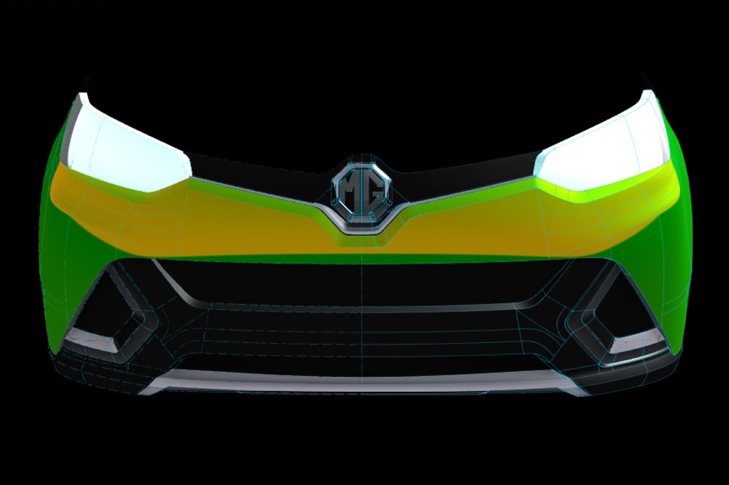
Don’t be taken aback by some unfulfilled design desires. After developing the functional objectives of the bumper, there is often a small window of improvement possibility in the product development cycle to be innovative with the vehicle architecture. After all, nobody rejects good ideas, so if you just came up with one, share it.
At this point, it’s time for designers and modelers to step in once more before the beginning of A class surface refinement. Just be aware that this window often closes quickly due to project time constraints. Mutual inspiration of ideas is priceless in the design studio environment, where each person’s contribution often might open new opportunities for the whole team.
If your design studio works with an industrial clay, this is your chance to take a quick last glance with an experienced eye on the entire clay model to evaluate proportions. Clay can’t be substituted by any means of virtual reality. Physical contact with the actual model will tell you everything you need to know about volume and quality of surfacing. Take a few steps back and give yourself 5 minutes alone to see areas of possible improvements.
Consider:
- Sections requirements
- Hard points compatibility
- Areas of impeccable highlights
- Aerodynamics
- Pedestrian safety
- Surface area of grill and its complexity
- Minimum fillets value
- Snap-in decorative elements
- Front overhang
Step 3: Technical Input – Manufacturing
All of the relevant engineering data provided in step one and two, such as: package hard points and sections drawings receive maximum amount of details with latest engineering solutions to the emerged problems during design. At this stage modelers want to make a case for themselves to gain 1 or 2mm here and there. Final exterior design is modeled over key elements of the package drawings. The main objective here is to work to solidified and frozen hard points which satisfy the requirements of the new design. Body structure can be developed as each section is investigated. E.g. collision beam section should include mountings, riveting and fillers. Assembly methods are considered. Questions weather snap-in elements are to be used, number, category and location of mountings, and whether current design leaves enough room for assembly tools operations are answered. Final digital model is complete. Is consists of styled A-class surface but also engineered B-surface.
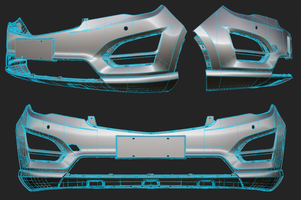
Success or failure at this stage is dependant on how well job was done in previous steps. It might happen that the whole project is simply “not good”, and need some thorough refreshment.
Consider:
- Approach angle
- Flange gaps and flush requirements
- Bumper-front quarter panel elevation difference, typically 0.5mm
- Minimum draft angle
- One piece bumper or color split – bonding for better assembly, where welding is infeasible
- Structural joining of vehicle bodies to improve rigidity, durability and crash performance with weld-bonding over rivet-bonding
- Bumper-body means of attachment, mounting design
- What material to satisfy the styling
- License plate
