For more free Mirror Mesh and Data download you can go here: https://themodeldesign.net/3d-modeling-automotive-level-free-model-download/
Get a comprehensive insight into A Class Surfacing and High Quality Reverse Modeling. Immerse yourself into intricacies of real A class modeling with this step by step, detailed modeling process explanation. Just watch this 3 parts video tutorial on my YouTube channel. Additionally, on my blog, you can get a PDF1 PDF2 and PDF3 overviews with major points from the tutorial series, and download a finalized 3D model together with the scan data to try your hand at.
Project Workflow Introduction
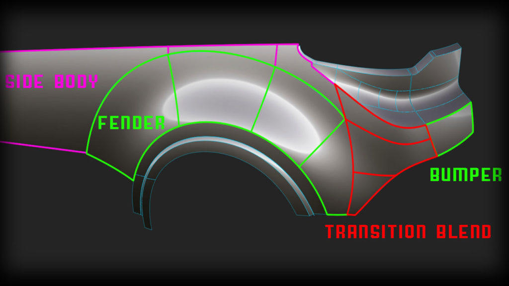
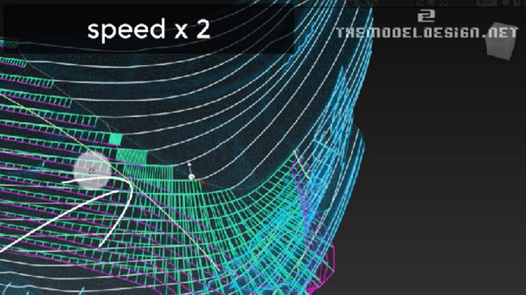
In this tutorial I work on one of the most complex areas of this car’s bodywork. Basically, the task is to blend three different surface patches that will be integrated into one elegant solution.
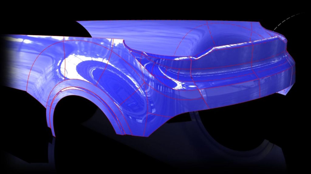
Each particular video tutorial introduces a modeling process of primary surfaces. These are: Bumper slab surfaces, side body surfaces and fenders. They form the foundation for our final portion of surfacing, which is the blend bumper. Produced geometry has A class qualities. By understanding the tribulations behind A class modeling, you will be able to analyze steps taken, and anticipate steps ahead to achieve very good results relatively quickly, and non-destructively manipulate geometry within 1mm of surface to model deviation.
Project Main Content Detailed Explanation
- Borrow curves to avoid nonuniform surface CV distribution in later stages.
- Create anchor trimmed edges for the blend surfaces. Observe scan to analyze exact location.
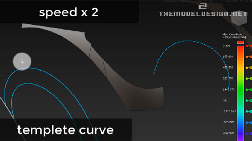
- When highlights look nothing like the scan, manipulate CVs to achieve results that are very close to what we are after.
- Auxiliary surface – helps us create fender surfaces at initial stages of modeling. We can evoke the history and modify the reference surface. This surface is not going to do much for us in terms of a finished product. Later we would be manually tweaking the blend and the reference surface will lose its initial function.
- Bubble will move down as soon as we drag the CVs down. If we overdo we can move the bubble up again a little bit.
- There is a huge difference when picking CVs for manipulation. Refer to the video for more explanation.
- Let’s not worry about any position failures G0 at the moment. We can always add more degrees later on, for now the result is good. Adding more degrees will make our surface a nightmare to manipulate to suit the scan because there will be too many CVs to worry about.
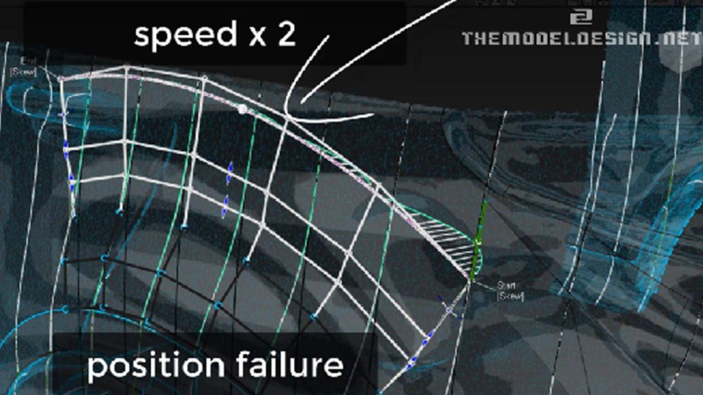
- With the history active everything remains connected and alive as we manipulate the CVs. The patch updates automatically as we modify it. Monitor zebra and scan-surface cross section lines misalignment with history active.
- Don’t rely on tools alone. Changing colors of surfaces and visually compare them to scan data. Compare overlapping data and their colors. If there is too much of one color (yellow in this case) or too much of the scan highlight it means that in this areas surfaces don’t stay close enough to the scan
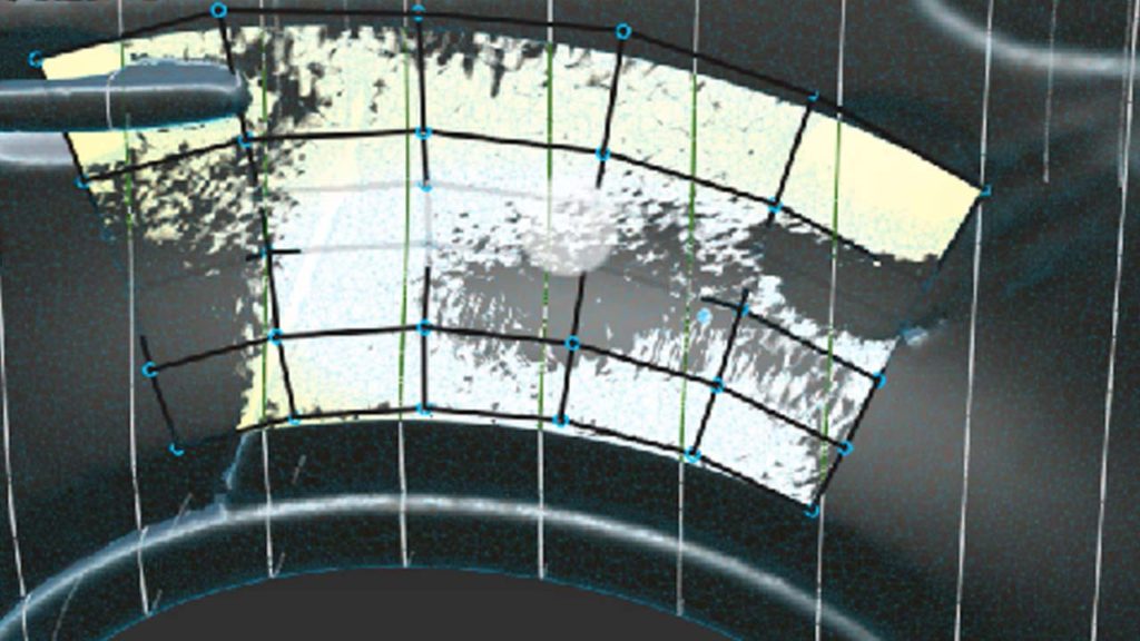
- Squeeze the view to see any highlights imperfection even better. Look at the zebra stripes. Make them nice and round.
- Remember to always think twice before you call the job complete. It always takes time to come up with something rather good. I have noticed some discrepancies some area. Let’s remove this difference in zebra by grabbing CVs and I slide them down. Just quickly tweak ‘here and there’ to get a better effect.
- We are very close. Look at zebra and at the same time the gap between these two lines which are scan line and our surface line. We can use a hull planarize with history active, this way we won’t destroy the continuity.
- Some surfaces still need some modifications, you can see that our zebra doesn’t do exactly what it needs to do. We could try to push this side surface in, so that stripes dive in slightly quicker, it will have more lead-in to it
- Let’s keep the position influence 0, otherwise we will get an exaggerated CVs movement, because Alias is trying to compute the alignment to eliminate the gap
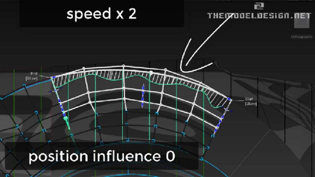
- Align tool can destroy our work and result is not always desired. Sometimes the align tool gets the CVs messed up.
- Go a bit further in terms of a curvature comb. Let just move it a touch to go that tiny step forward.
Situation Recap for Second Video
- In the second video we create second portion of rear fender and we prepare our geometry to blend into rear bumper
- This scan isn’t that accurate. This is not how the usual highlight looks on a real car. Highlights don’t widen, get narrower then widen again.
- There is a slight dip in here. We will try to push these CVs out just a touch. Quick look at our CV from an acute angle. Can you see it is dipping inside? When you push CVs out, see how this comb is changing. Can You actually see it? It is looking much better.
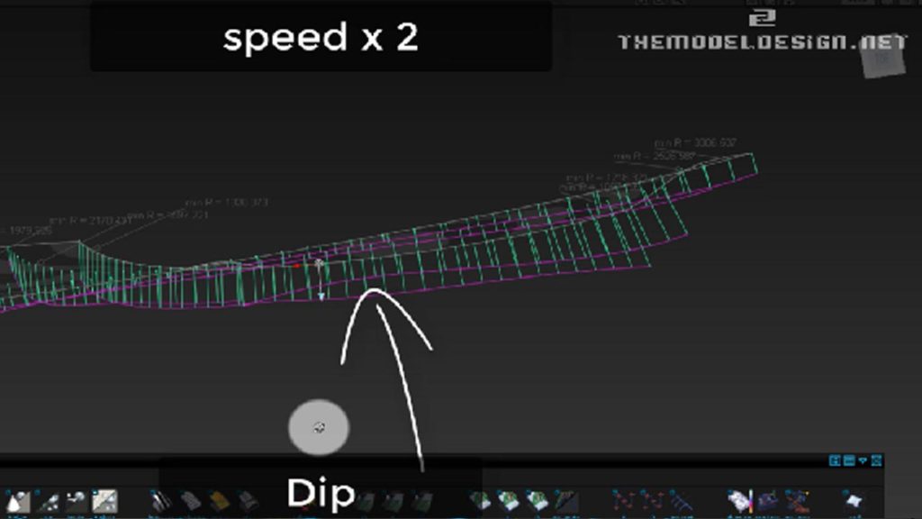
- We should do some more work around the corner blend. At the moment, CVs are kind of messy and we need to improve them. this patch would have to be moved to somewhere here, so we need to extend this down a bit. To do that, Just manually manipulate CVs by pushing, pulling, or sliding, change the view multiple times, and if you see any concavities, push CVs outboard
- Make this patch longer than we need, and work on it in this condition for a better insight into geometry. Make sure the CVs look nice, and then when they look nice in extended stage, we can then go ahead and shrink this surface to the length we need
- Smooth this surface with a smooth tool and history active. By smoothing I lost the original CV distribution around perimeter, therefore I need to realign edges
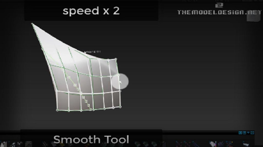
- I suddenly had an idea and decided to simply remove this patch and extend our work in progress blend to the split line. I don’t think I need any extra surfaces in here just to make it super clean
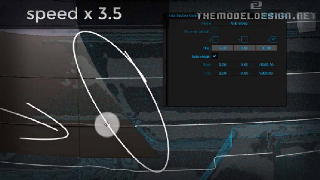
- Let’s get down to the side body surface. Align and make sure that the side body surface has a clean G3 curvature connection with the transitional blend.
- It looks like removing one or two degrees doesn’t affect our comb curvature. But what happens If I tried to delete more degrees. I think that our surface will also be ok
- Do you see the concavity in this comb? Is this acceptable? I think we have overdone a little bit. Do you see the scan surface lattice lines? They don’t overlap. You can push in Hulls and at the same time, observe the edge-surface distance. If we just try to push that CV in… Do see how this follows? OK, There you go… So this is almost G3, we just need slightly better connection here, let’s grab the second row of CVs and do the same
- Add more degrees to adjust properties of the corner blend
- Finally, we achieved G3 continuity in the indicated area and we are ready to build the last portion of geometry to close off the model
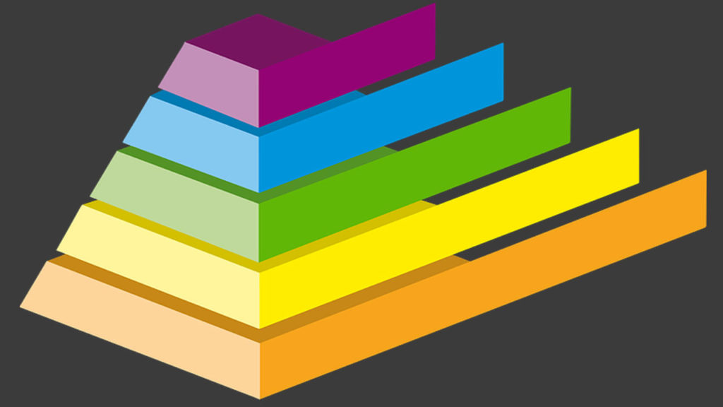
- We are ready to create our last portion of fender surfaces using this technique. I call it a pyramid method. Basically we start wide and loose, and slowly move forward to become narrow and accurate. We create a loose surface and manually adjust CVs. As I get closer to desired shape, I can even add spans to achieve decent form. I walk through the sculpting process with just single patch and only when I am sure it is very close to what I want will I detach it.
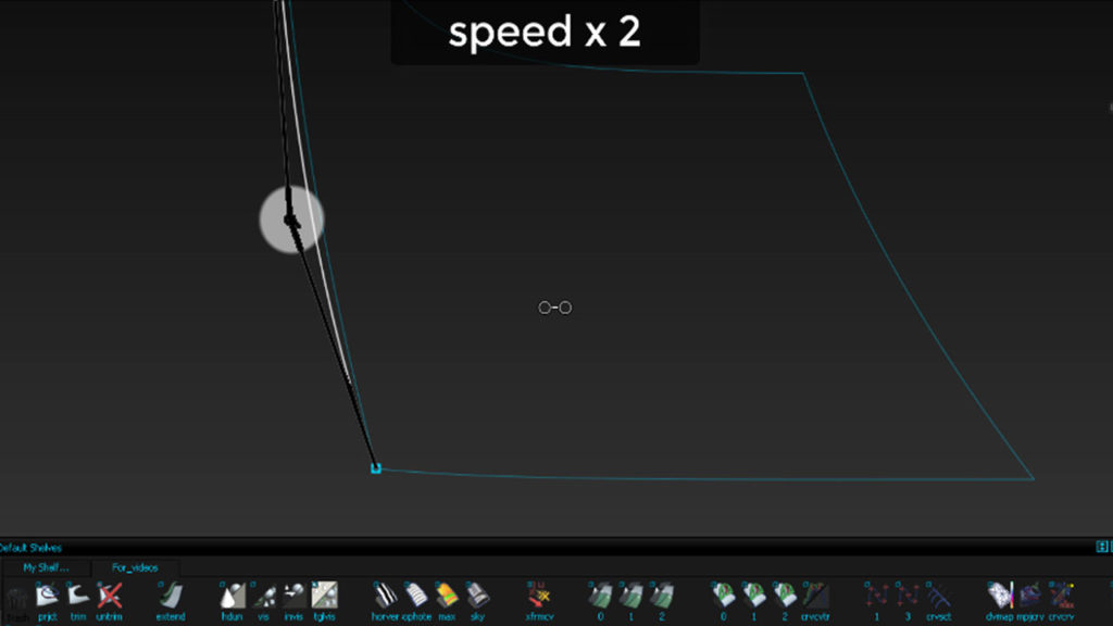
- Duplicating the wheel arch curve, move the copied curve, and template our original curve. Delete the bit we don’t need. Let’s keep this curve very close to the geometry. Check the comb curvature and adjust it if necessary.
- We want to have one continuous surface rather than having two or more separate patches, and having to work with them separately. Let’s move this curve close to the trimmed edge. The curve should be as close to the trimmed edge as possible.
- But wait a minute. I’d like to have a curve that is perpendicular to edge and runs from the anchor point to wheel arch. To accomplish that I use a blend tool to be my reference anchor point. Then, I simply draw one degree curve without worrying about adding any degrees as yet.
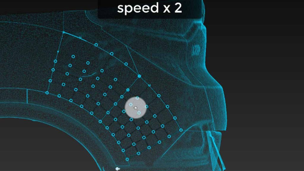
- Let’s use a square tool to patch this area up. All the curves can be templete and placed on a layer. Don’t delete them, you might need them later.
- Let’s use my tricks just to improve this patch, and planarize hulls in side view to get all CVs neat in this view.
- Manual tweaking is never enough. Push out our surface to match the scan as much as possible. Don’t worry about continuity. Try to just match zebra keeping in mind that your patch mustn’t deviate from the scan. I underline this because it would be possible to achieve a very close zebra representation without staying true to the scan. We would end up with good reflection but bad volume model. As you can see our wheel arch wasn’t that accurate, just do what you feel is right. Push this out and don’t worry about the gap between wheel arch. The principle is, if you see deviation just fix it. If you are afraid of remodeling the wheel arch surface you just accumulate problems for later.
- We are closing to the most difficult part of the modeling process and the truth time is approaching. In fact the truth is bitter because our surfaces, especially zebra don’t match. Can you see? OK, let’s tweak and see what we can do.
- If you come across situation when you perform a comb curvature analysis on two separate surfaces and they have opposite directions, just use the tool to swap U and V directions of one of them.
- When tweaking the patches, try to not touch the left portion of it, otherwise we will lose the G2 condition over there. However, I can do a lot of work on the other, right side.
- I slide CVs because sliding won’t affect them in side view.
- Let’s copy and paste the square patch and templete the copy. Create a back up just in case if our destructive idea doesn’t work. We are going to destroy the patch by detaching it.
- Grab a detach tool, press and hold CTRL Button to separate the patches and have more ‘sculptability’.
- Align G2, and don’t worry if you don’t achieve continuity, just keep it degree 5 for now, keep it simple.
- Aligning doesn’t give good result. Geometry is still not very accurate. In such situations sliding might do the job. Also active history is very helpful. This highlight is not exactly what we are after. Let’s what we can do to improve it.
- Just arranging CV slightly better at the same time paying attention to the zebra. At this moment you must have notices that reverse surfacing is all about adherence to zebra, closeness to scan and a good CV layout. Just observe how CVs behave and how they can be manipulated.
- Quick look at zebra will make you realize that it is still not exactly how it is supposed to be. Especially in here. Observing and noticing things to improve can be done by almost anybody, but coming up with an efficient strategy to eliminate these problems, and putting this strategy into practice is always more difficult.
- We need to go back and tweak surfaces we built in previous video, but not the whole geometry. We will detach the blend and work on better transition. But before that, copy and back up your corner blend surface.
- Let’s trim convert this path. Sometimes this tool doesn’t work. When you run into trouble of not being able to use trim convert tool, just make sure that the patch you want to convert is of 4 sides. Sometimes, when COS runs into a corner there might be a short section of an edge, invisible to bare eye, which will make the surface 5 sided. Just extend the COS and the patch. We have some wobbling, you can see the CVs. I think I will just delete it and try something else.
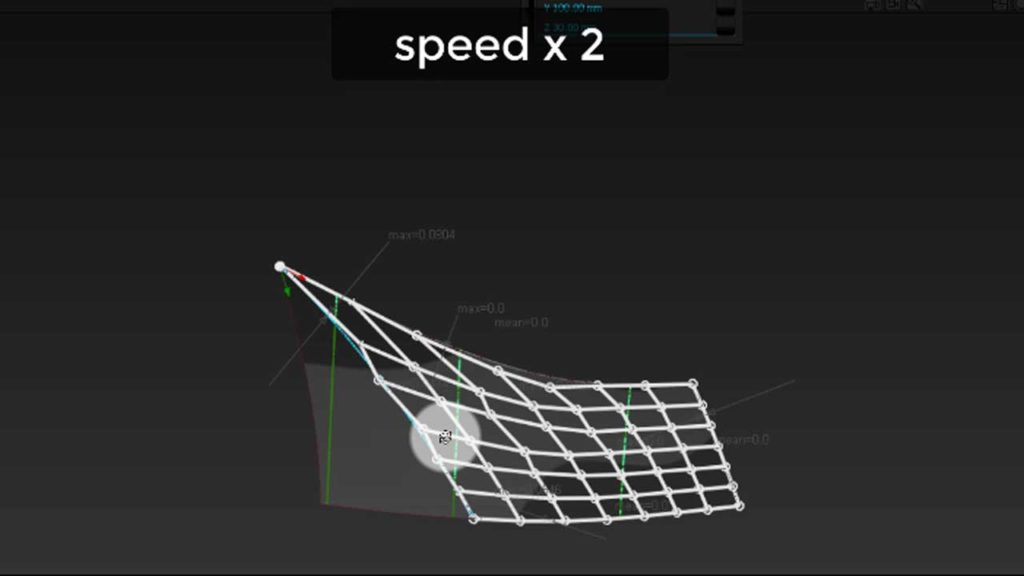
- Instead, Let’s extend this tip patch with merge off to somewhere here and try our luck again. Can you anticipate what the workflow is going to be?
- Behind the scenes I fixed the problem. Let’s turn on the curvature comb to examine quality.
- Compare geometry to the scan data. We can see that scan is doing something slightly different to what our surface is doing. There are some discrepancies here and there but generally, not too bad.
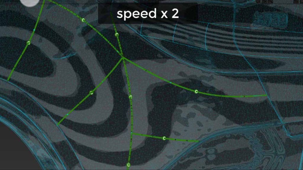
- If you want you can download it off my blog – The link is in description, I hope you enjoyed this tutorial, I hope it was helpful. Stay tuned…
